A chronograph is one of the most important tools a reloader can own. However, ALL chronographs have their quirks and foibles. The information below applies to all brands and should help you get the most from your chronograph. It is listed in alphabetical order
First Things First
If you are experiencing problems with your chronograph, READ THE MANUAL before calling the manufacturer. Then if that doesn't resolve your issue, check the following, as these are the most common issues.
Are you too close to the chronograph. Your first screen should be no closer than 8'. If using a firearm with a lot of muzzle blast you may need to have the first sensor farther from the muzzle.
Are you shooting directly over the center of the sensors and is the bullet's shadow falling on the sensors?
Are all cables and connections clean and tight
Power. If using batteries ensure that they are fresh alkaline batteries and that all contacts are clean. If using AC power ensure that the plug fits snugly in the jack, and that the power unit is operating correctly.
Below is some more detailed information
Dirty Contacts
If you you haven't used your unit in a while your sky screen contacts on the jacks and plugs my develop a slight layer of corrosion or a film and you may get either an erratic reading or no reading at all. Wiping the plugs may help correct this. A better solution is to use a product called DEOXIT. This is a contact cleaner and preservative that comes in a pen-like dispenser and which is used in the audio and video connection business. It is available at Radio Shack, their catalog number 64-4336 and costs about $10. Put some on the jack pins and insert and remove them repeatedly while twisting a couple of times. It is also a good idea to use this product on the battery contacts.
![]()
Long Projectiles
When chronographing very long projectiles like arrows and crossbow bolts the screen spacing much be such that the first sensor is completely cleared by the projectile before the second sensor is reached. A 4 foot spacing works in most cases. With chronographs that trigger off the base of the projectile the opacity and positioning of the fletching as it passes over the sensor can also effect performance.
Muzzle Too Close to First Sensor
Both visible light and heat exits the muzzle of a firearm along with the bullet. If the first chronograph sensor is flooded with a flash of light or heat "bloom" the velocity readings may be incorrect, produce an error, or give no reading at all. This can be particularly annoying with sub-sonic ammunition.
Industry standard "instrumental distances" are 10, 15, 53, and 78 feet from the muzzle--the "distance" being the mid-point between the 2 screens. Thus for an instrumental distance of 10' with a 2' screen spacing, the first screen should be 9 ' from the muzzle, and with a 4' spacing at 8'. For shotguns in may be necessary to use a closer first screen distance distance and and due to the lower pressures involved 4' from the muzzle to first screen usually works.
If space consideration limit the distance you can place your screens from the muzzle you can make up a plywood blast shield and place it in front of the first screen. Simply cut a hole about 4 inches in diameter in a 1 foot square piece of 3/4 inch plywood located so the bottom of the hole is 2 to 3 inches above the sensor body and place this in front of the first screen on its own stand.
Poor Lighting Conditions
Low Light - All chronographs using conventional skyscreen technology need light. The chronograph measures velocity by sensing a bullet's shadow as it passes over each sensor. Most problems with conventional skyscreen chronographs of all brands relate to lighting conditions. In short, if you cannot see your shadow on the ground there will be no bullet shadow for the chronograph to see. If a chronograph is used in low light and not equipped with an IR screen option, look on the ground to see if you are casting a shadow. If there are no shadows on the ground there may not be a bullet shadow for the chronograph to detect. If shadows are faint and the sky is light colored, removing the screen tops (glare shields) will often allow the chronograph to work.
Light Balance - The amount of light entering the sensors should be equal. Avoid having the sun directly in front of or behind the sensors as the difference in light reaching the senors will cause problems, and in some cases the screen nearest the sun can actually shade the sensor behind it.
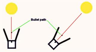
Low Sun Angle - You must always shoot parallel with the sensor bracket. If the sun is low on the horizon and you are shooting north or south there may be insufficient light entering the tops. Bend down and look at the underside of the tops. It should be obvious if insufficient light is entering through the tops. Tip the tripod head toward the sun to allow more light to enter the sensors and to place the bullet's shadow directly on the sensors.
|
|
|
Tilt the heads to get sunlight over the sensor cell |
Lens Flare - It is still possible at certain latitudes, direction of fire, or time of the year, for the sun to shine directly into the sensor slots causing "lens flare" which prevents the screen from reading. This can happen even when using IR heads. If this happens you can often eliminate the problem by tipping sky screens, changing direction of fire or taping cardboard to the screen assembly to block indirect light from entering the sensor slots.
Ground Reflection - If the screens are over bright white new concrete or snow, cover the ground with something dark or kick back the snow. A plastic trash bag works well for this purpose. Ground reflection can illuminate the under side of bullets as they pass over the sensors so there is insufficient shadow contrast for the chronograph to work properly.
Inconsistent bullet path/aim point - If each bullet doesn't pass close to the same place over the screens, you may get erratic reading. This is especially true for low sun angle shots.
Gunk In The Sensors - I have seen several seldom used chronographs that had junk or cobwebs in the sensor openings. Make sure the area is clear.
Sensors Not Held Stable
Sensors Not Mounted Tightly To Rail - Verify your that your sensors are mounted squarely and tightly to the rail. If a sensor can rock 3 degrees forward or backward the effective screen distance at the bullet's path will change inducing a error in the velocity recorded. If the bullets path is 9" above the sensor, a 3 degree cant of one of the sensors will change the effective screen spacing by .47 inch, which will induce an error of about 1 percent or 60 f/s at 3000 f/s with a 2' screen spacing. If both of your sensor head can wobble back and forth by 3 degrees each direction there is the possibility of a 120 f/s total error. (FYI, a 1 minute graduation on a clock face is 6 degrees.)
With units with a foldable mounting bar you should mount the with the non-moveable part of the bar towards the muzzle to prevent muzzle blast from raising the arm, and you can fill the foldable end with some weight to keep things in place.
 |
Poor Tripod - While the support legs and tops can't move from muzzle blast, the entire sensor assembly MUST be held stationary too. If you are getting readings drastically lower or higher than what you know the round is shooting it is probably because the sensors are moving. This problem can be eliminated by mounting the screens on a better tripod or weighting each end of the rail with a sand bag.
Sensors Not Properly Spaced
Sensors not properly spaced will give erroneous readings. Ensure that your sensors are fully seated on your rail at the proper distance and fully tightened. If the sensors are not tightened to the rail the spacing can change during shooting. (Check frequently!) Also, if you have a 2-piece rail ensure that the rails are secured together properly or you can fill the rails with some weights to keep things in place.
With a chronograph, velocity is determined by dividing distance between two detection "screens" by the time it takes the bullet to pass through both screens. (Originally the "screens" were just that, a screen of fine wire or a circuit path printed on a sheet of paper that was broken by the bullet. Modern chronographs use optical sensors to detect the bullet's passage, but the term "screen" has stuck.) The timing is done with high frequency counters ("clocks") to measure time precisely and modern chronographs with their extremely fast clocks theoretically allow the use of shorter inter-screen distances since time is measured more precisely due to there being more "counts" per second. If a clock is erratic or is off its designed frequency errors will result, but modern clocks are remarkably accurate and consistent .
The greatest source of chronographing error is inaccurate screen spacing. If the inter-screen distance (the distance between the first and second screens) as set into the chronograph is 4 feet and the distance is mis-measured by one-half inch, the inter-screen distance is off by about 1 percent. At a velocity of 3000 f/s this introduces an error of about 30 f/s. With a 10 foot screen spacing a similar half inch error would cause about a .42 percent error or about 12 f/s. It can be seen from this that the shorter the screen spacing the greater the potential velocity error for a given inter-screen distance error. Granted, these errors seem small but such errors can lead to discrepancies between measured data if you are not consistent each time you set things up. Use the greatest inter-screen distance you can conveniently use. I consider 4 feet to be the minimum safe spacing with low frequency (4 - 10 MHz) clock chronographs, but with a modern high clock speed unit like the CED, 2 feet will work fine if set up correctly.
Some of the newer 1-piece or unitized chronographs have use a 1 foot spacing and a 1/16th inch error in spacing can cause a .52 percent error or about a 15 f/s error at 3000 f/s. While the one piece units are usually carefully adjusted at the factory there is the potential for misalignment if the units are dropped or subjected to shock. Treat chronographs like the precision instruments they are.
Also, the screen sensors must be pointed up at 90 degrees to the mounting rail. If one of the screens is tipped either toward or away from the muzzle of the gun the inter screen distance will be different that what is set into the chronograph since the bullet path is some inches above the sensors.
 |
|
If the sensor head is tilted (red line) the effective inter-screen distance will be different than what you think. Keep in mind that a tilt of 6 degrees is the angle 1 minute makes on a clock face |
If the bullets path is 9" above the sensor a 3 degree cant of the sensor base will change the effective screen spacing by .47 inch, which will induce an error of about 2 percent or 60 f/s at 3000 f/s with a 2' screen spacing. If one of your sensor head can wobble back and forth by 3 degrees each direction there is the possibility of a 120 f/s total error.
(bullet height above sensor) * (tangent of the angle of cant) = error
Tangent of 3 degrees = .0524 (from Trig tables)
9" * .0524 = .47"
The other "spacing" issue involves the distance from the firearm's muzzle to the mid point between the screens which determines the distance at which the velocity is actually measured. It is common industry practice to set this distance to 15 feet from the muzzle although many handloaders use a more convenient 10 feet for this distance, and the military historically uses either 53 or 78 feet. The actual distance used is not as important as not being too close because it is possible for the muzzle blast to affect a screen's detection of the bullet's passing if sub-sonic projectiles are being measured.
As for correction from "instrumental" velocity to "muzzle velocity the correction is very small at a 10 foot or less distance to the center of the screens--on the order of 5 - 10 f/s for typical rifle bullets and velocities--and this falls well within the standard deviation of most loads. If you consistently use the same muzzle to screen pair distance you really don't need to worry about this correction.
Shooting The Sensors
Don't laugh. This happens all the time, especially when shooting firearms with high lines of sight like the M16/AR-15 which have sight heights in the 2.5" or higher range, depending on the sights used. At the close distances shot over chronographs that bullet will be much lower than the point of aim. Ideally you want the bullet to pass 4 to 5 inches over the sensor window so you point of aim has to be chosen for the sighting system you are using When shooting firearms with high lines of sight you can hang a small aim point from the glare cover of the first screen to ensure that the bullet path is above the sensor head. A friend sticks a laser bore-sighter in the muzzle to ensure that the bullet will not annoy any sensors.
The same thing applies when chronographing at long range. You need to know the path of the bullet to avoid becoming a sensor murderer.
 |
|
Oooops! #$@%&#! |
And then there is design considerations
One thing most people don't consider about chronographs is their inherent standard deviation error--that is the random error that would occur if a projectile of exactly a given velocity was measured several times. This is a function of its circuit design, clock frequency, and clock stability. The best currently available units in this respect are the CED Millennium and Millennium II. I have seen some inexpensive "bargain" chronographs that had 40 f/s or more of built in error.
Please email comments or questions to Fr. Frog by clicking here.
| Back to Fr. Frog's Homepage | Back to Misc. Q&A |
Disclaimer
As far as I know all the information presented above is correct and I have attempted to ensure that it is. However, I am not responsible for any errors, omissions, or damages resulting from the use or misuse of this information, nor for you doing something stupid with it. (Don't you hate these disclaimers? So do I, but there are people out there who refuse to be responsible for their own actions and who will sue anybody to make a buck.)
![]()
Updated 2024-01-04 @ 1325